Heat Flux Thermography
Heat flux thermography – or also “active thermography” – is based on the three-dimensional heat flow within a part to be tested. A number of different stimulation technologies can generate this heat flow over the area to be tested by the inhomogeneous warming of the component. The heat flow is disturbed if defects are enclosed in the material.
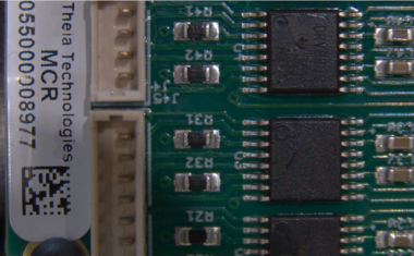
An infrared camera maps the changes of the heat radiation on the component surface with fast times and high thermal resolution (normally in the range of milliseconds and millikelvin). The infrared video permits conclusions to be drawn – in part also by the comparison with mathematic models of heat dissipation – about the three-dimensional heat flow and thus flaws hidden in a part. Typical components are: Car body structures, solar modules, turbine blades, steel strips, painted sheet metal, micro-electronic circuits, carbon fiber compound materials… the list could be continued almost indefinitely.
By contrast, with “passive thermography” only the heat radiation emitted from all objects is captured. This also permits a defect detection in some cases – but only of defects on the component surface.
Heat Flux Thermography – a Non Destructive Test Method
Heat flux thermography, apart from the known methods of non-destructive testing (NDT) such as x-ray, ultrasound and eddy-current testing, has also become established during recent years as an independent NDT method in the industrial field. This is especially due to the availability of a wide range of high-output infrared cameras and application-optimized infrared lens attachments (e. g. microscope lenses). Furthermore, the available stimulation methods were developed further or adapted and optimized to the demands of heat flux thermography. However, the key step toward broad industrial employment was the development of automated systems, suitable for production runs, for specific applications. The benefits of heat flux thermography (touchless, non-destructive, imaging, etc.) for a technically and economically successful application were demonstrated hereby. Heat flux thermography can partly replace destructive test methods (e.g. “hammer and chisel test” of welding joints) and, to an extent, a suitable test method only became available with heat flux thermography.
Infrared Cameras and Lenses
The main components of measuring technology are high-resolution infrared cameras and infrared lenses with high luminous intensity. Both components must be adapted to the same wavelength range: For example, infrared cameras are supplied for the short, medium and long-wave infrared range (SWIR, MWIR and LWIR). Furthermore, there are special cameras covering two adjacent wavelength ranges: S/MWIR and so-called dual band for the medium and long-wave infrared. To be able to crisply map a fast process or, in general, to utilize high frame rates, sensitive detectors and imaging systems with high luminous intensity are needed. For this reason, cameras and lenses from Thermosensorik GmbH are designed for large apertures (F/2.0 or F/1.5).
When choosing the right camera, the following must be considered as well: The number of pixels required for the geometric resolution, the image frame rate (at specified image size) required for the time-specific resolution and, closely related to this, the achievable integration time (exposure time). Last but not least, mapping scale and the distance between camera and object must be accommodated: Are telephoto lenses or microscopic lenses with spatial resolutions below 3 µm required or is a standard lens the right choice? But even smaller scenarios can be achieved: Apart from the unique range of microscope lenses, solid immersion lenses and the heat flow spreading to all sides ensure that heat sources even in the nanometer range can be determined.
Stimulation Technology
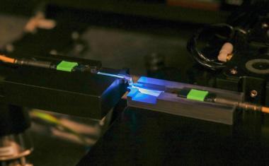
The choice of the right stimulation method is especially important in heat flux thermography: What requirements do the test specimen and the test environment present? Material properties such as electric conductivity, heat capacity and conductivity as well as the absorption capability need to be considered here just as much as accessibility, work safety or operating costs and fatigue properties. The choice encompasses not only flashlamps, halogen lamps, LED arrays and lasers but also heating under operation voltage, eddy-current stimulation, ultrasound, hot and cold air as well as mechanical stimulation. Induction or eddy-current stimulation belongs to the touchless stimulation methods and is to be preferred over illumination stimulation, especially with strongly reflecting metallic test specimens.
The example below shows how a brass tube clad in plastic and having holes passes through the induction stimulation. In this case only the conducting brass tube is heated from which the heat wave travels through the plastic jacket to the surface. The output image is created by adding many line images taken during the passage time and it also shows the holes below the plastic jacket.
The optical stimulation methods are primarily recommended for electrically non-conducting materials: Halogen lamps, flashlamps, lasers, LED arrays. Stimulation via halogen lamps is especially suited for lock-in thermography with modulation frequencies up to 1 Hz. The surface stimulation with flashlamps is probably the most common method also because systems designed for three-shift operation have been available for quite some time. Flashlamps are able to generate a sufficient heat gradient – and thus an adequate heat flow – with high energy and in a pulsating manner, even in materials with good heat conductivity. Lasers and LED arrays allow both for the fast modulation of the stimulation output and for the smart choice of the stimulation wavelength, adapted to the specimen material and the sensitivity range of the IR camera. Furthermore, laser stimulation permits introducing heat focused on a single point or over a large surface (broadened or scanning).
Laboratory and System Software
Market demands have specified two development directions for the software: A versatile laboratory software product (“Multi-purpose software” MPS), software for periodically stimulated measurements (lock-in suite) and add-on options (script language, software development environment, …) are used primarily in research settings with constantly changing application areas.
Apart from this, the Thermosensorik System Software SCS was developed especially for use in industrial production. It is equipped with a fieldbus interface, customary in the industry, and two operating modes: Operator mode and expert mode. This prevents faulty operation in production, on the one hand, and, on the other hand, the expert is able to optimize or redefine parameters for additional components at any time. Professional advice and feasibility studies in the application laboratory of Thermosensorik help find the optimal combination of camera, lenses, stimulation method and analysis software.