Monitoring Superconductors Via Digital Image Analysis
CERN (French Conseil Européen pour la Recherche Nucléaire) is located in Meyrin near Geneva in Switzerland and is the world's largest research institution for particle physics. There are currently 6,500 visiting scientists from more than 80 countries using the CERN accelerator facilities for their experiments. 2,600 regular employees ensure that everything runs smoothly. The institution was founded in 1954 by 12 European nations as a joint project and celebrated its 50th anniversary in 2004. There are 20 member countries of the CERN organisation that cover the operating costs. It is ensured by laws mandate that research done here may not serve military purposes and that all results must be made publicly available.
In the Very Center of Things – What Keeps Things Together?
CERN's primary task is the construction and operation of particle accelerators and detectors for investigating the most minute structures of matter. In these accelerators, particles are accelerated almost to the speed of light and collided head-on. Due to the high amounts of energy thus released, new particles are born that are verified and investigated by the detectors. The results of these experiments help to answer fundamental questions, for instance what matter is made of and what forces hold it together. Or as the 18th century German author and scientist Johann Wolfgang von Goethe had Faust, his world-renowned character, state: “That I may know, what holds the world together in its innermost regions.”
LHC: Unattained Particle Energies
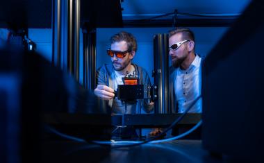
Currently, there is a new accelerator under construction at CERN – the most powerful tool ever built for investigating particles of matter and their properties. The Large Hadron Collider (LHC) is a circular accelerator in which protons are accelerated to 7 Tera electron volts. The LHC, which is to go into operation in 2007, is presently being installed in a subterranean circular tunnel with a circumference of 26.7 km, which has already housed the former LEP accelerator. An extremely powerful magnetic field of 8.4 Tesla is necessary to make the protons follow the curved path of the accelerator. Superconducting guiding magnets are needed for such a powerful magnetic field. Altogether there are 1,232 of these magnets installed along the accelerator ring. Each of them is about 14 m in length and weighs 30 t. In order to allow the high current of about 12,000 amperes to flow through the superconducting magnet coils, the magnets are cooled down to 1.9 Kelvin with superfluid helium.
220,000 Kilometers of Superconductors
For the fabrication of the LHC magnet coils, about 220,000 km of superconducting wire are needed. The wire, which has a diameter of approximately 1 mm, consists of about 8,000 fine fibres (filaments) made of a niobium-titanium alloy that are embedded in a copper matrix. Numerous metallurgical processing steps are necessary, such as extrusion and drawing, to reduce the diameter of initially 25 cm niobium-titanium bars down to 6 μm, which is the final filament diameter.
A Magnetic Effect that is Not Desired
During this process, the initially round niobium-titanium bars can become strongly deformed. The dimensions, the shape and the distribution of the fine filaments within the copper matrix affect the physical properties of the finished wire, such as the superconductor magnetisation. Quantitative optical metallography of wire cross sections allows to determine how the geometrical and physical properties are interdependent upon one another. To obtain statistically reliable results many niobium-titanium filaments have to be evaluated. This is why the scientists record the light microscopical images of the cross sections digitally and use automated detection and analysis for the image processing.
A Digital Look at Wire Cross Sections…
Preparing the wire cross sections for investigation involves first embedding them in epoxy resin. This ensures that the cross sections are precisely perpendicular. Then the cross sections are ground down with wet 600 and 1,000 grit silicium-carbide paper. Mechanical polishing is done with polycrystalline diamond-particle suspensions (9 μm und 3 μm) and a colloidal silicium-dioxide suspension (0.1 μm). Without any further chemical processing, the cross sections thus prepared are then placed under an Olympus BX51M reflected light microscope. A ColorView digital colour camera by Soft Imaging System mounted onto the microscope transfers the microscope images directly to the computer.
…on to Automatic Classification
Fig. 3a shows a true-colour acquisition of a cross section the way it looks when it is transferred by the camera to the analy-SIS image buffer. analySIS is the software environment installed on the computer and developed by Soft Imaging System for digital image analysis and digital image management. The software offers the functions necessary for acquiring, further processing, interactive/ automatic analysis, archiving and documentation of the digital images and related investigation results. The software subjects the original image to a shading correction first. This means that the uneven illumination of the sample under the microscope is subtracted digitally. Then the true-colour acquisition is converted to an 8-bit grey-value image and the niobium-titanium filaments are separated from the copper matrix based on defined thresholds – all by the software. The Region Of Interest, or ROI, is the area which is to be investigated and is defined interactively (yellow line in Fig. 3b). Then a digital particle analysis is conducted. The software detects the various filament cross sections as separate particles and measures shape and size automatically.
A Round and Less a Round
A sample shape analysis: quantitatively investigating deformation means determining the shape factor of each particle. The shape factor describes just how round a particle is. Particles, i.e. cross sections that are perfectly circular, have a shape factor of 1. The less round a particle is, the lower its shape factor. The mathematic formula is: 4*π*A/U2, where A is the area; U is the circumference of the particle. All measurement results are automatically entered into a sheet. Based on shape factor, particles (i.e. the filaments) are all classified, thus categorising them into shape classes. The results of all measurements are then statistically evaluated – either within analySIS, or data is exported into another application. One thing statistical evaluation allows is correlating the degree of filament deformation with the superconductor magnetisation (measured separately).
Class at a Glance
If desired, the software presents classification results graphically. The filaments measured within the ROI are highlighted in colour (Fig. 4). This enables researchers to see at one glance which filament belongs to which shape class and the distribution of the various shape classes within the ROI, thus indicating to what extent the wire being investigated is deformed. The least deformed filaments are black; those with the highest degree of deformation are red. The colour highlighting does not affect image data in any way. The software displays the highlighting in the image overlay, which is like a digital transparency placed over the image.
Estimating Magnetisation
Evaluation of the measurements can show how the filament deformation during the production process can affect the superconductor properties. To put it simply, the greater the filament shape deviates on average from the ideally round shape, the greater the undesired superconductor magnetisation. Take the filaments in Fig. 4b, for example. They are more deformed than those in Fig. 4a. The average shape factor of the filament cross sections in Fig. 4b – which was determined via image analysis – is 0.41. And this value is less than the shape factor determined for Fig. 4a: 0.51. The related superconducting magnetisation is greater, however. Once there are sufficient measurements available, it is possible for the researchers at CERN to estimate the magnetisation from the average filament deformation in the wire cross sections.
This text was made possible by the kind support of Christian Scheuerlein, European Organisation for Nuclear Research (CERN), AT-MAS-SC (magnets and superconductors), Geneva, Switzerland; Christian. Scheuerlein@cern.ch.
Esther Ahrent Section Manager Marketing Communication Olympus Life and Material Science Europa GmbH Microscopy Tel. +49-(0)40-23773 5426 microscopy@olympus-europa.com www.olympus-europa.com