Fixed Focal Length or Telecentric Lens?
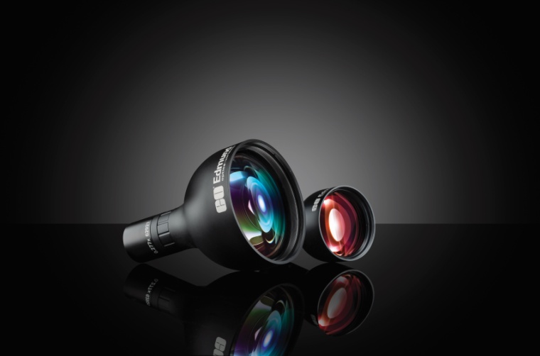
How do telecentric lenses work? And how exactly do they differ from fixed focal length lenses? This article introduces the peculiarities and explains why telecentric models are predominantly used in optical metrology.
Similar to human vision, fixed focal length lenses (also referred to as entocentric lenses) have an angular field of view, resulting in objects further away being imaged smaller and vice versa. In a metrology setup, this property is undesirable because the measurement result, e.g. the diameter of a component, is not meant to change even if the test specimen is not positioned exactly but only within a certain tolerance range in front of the test system. In optical terminology, this phenomenon is referred to as parallax or perspective error, meaning the change in magnification depending on the working distance.
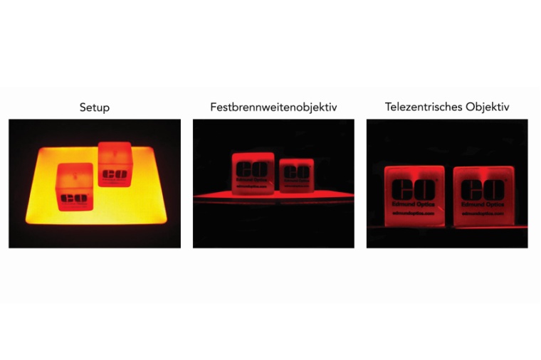
In telecentric lenses, this undesirable property is eliminated or greatly reduced by their design. Figure 1 shows two identical objects at different distances from the respective measurement setup. The left image shows the scene taken with a fixed focal length lens, for the right image a telecentric lens was used. Despite the significantly different distance of the two cubes from the lens, they are shown the same size in the right image. This visualization is achieved by ensuring that the chief ray runs parallel to the optical axis in the design of the lens. This is the defining characteristic of an object space telecentric lens. However, this also means that at least the first lens element must be at least as large in diameter as the workpiece itself to be inspected.
Depth of Field
It is often mistakenly assumed that telecentric lenses have a greater depth of field than fixed focal length lenses. Ultimately, however, the depth of field is determined by the f-number of a lens; telecentricity only has an indirect impact. The f/# is, among other things, decisive for the diameter of the lens. This diameter is anyway large with telecentric optics compared to a fixed focal length lens, all other parameters being equal. Therefore, it is common for telecentric lenses to start only at f-numbers of about f/6. This is to reduce the diameter, design complexity, but also the cost of a telecentric lens. Fixed focal length lenses can often be opened up to f/1.4 – which is unattainable for telecentric lenses.
It should also be noted that when comparing the f-numbers of telecentric and entocentric lenses, it is easy to confuse two different parameters. For fixed focal length lenses, the value usually engraved on the lenses denotes the image space f-number for infinite working distance. The choice of this working distance makes sense for several reasons, a quite pragmatic one being that fixed focal length lenses can be used over a large range of working distances and there is no other "universal" working distance that is applicable to all lenses regardless of focal length or manufacturer. For telecentric optics, however, this choice does not make sense; after all, the working distance is finite and fixed for these lenses. Accordingly, in order to ensure comparability, a parameter known as working f-number is used. It is calculated by weighting the theoretical f-number based on infinity with a factor that depends on the specific magnification of the respective lens. For a correct comparison with the f-number of a fixed focal length lens, the value engraved on this lens must be converted by the same factor.
There is another interesting property of telecentric lenses that can give them advantages over entocentric optics in some applications. Due to the lack of perspective, objects become uniformly blurred when you reach or go beyond the limits of depth of field.
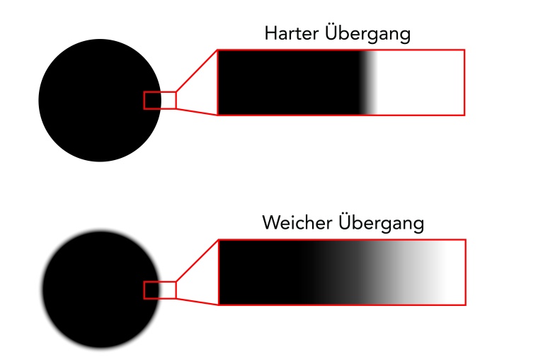
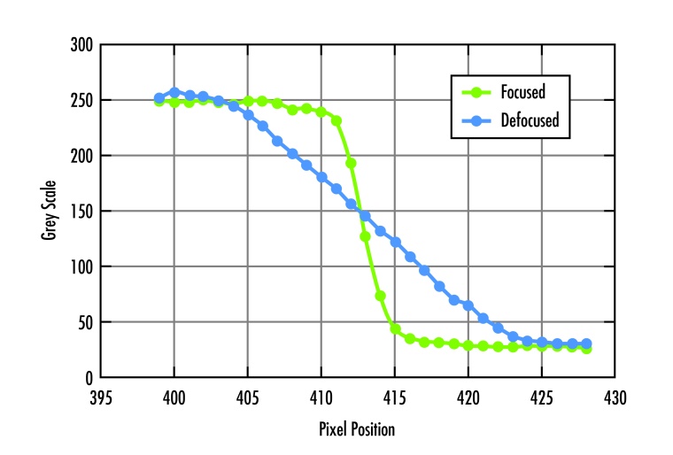
If you look at a round object with telecentric optics and leave the focus area, the object will become symmetrically blurred. An algorithm can therefore still determine the correct position of the center of mass. With fixed focal length lenses, the object would be distorted asymmetrically into an ellipse depending on its position in the image, and it would not be possible to determine its exact position. In this respect, it is possible to extend the nominal depth of field in special situations without necessarily having to accept losses in the quality of measurement results. Depending on the application and algorithm, it may even be advantageous to work with a certain amount of blurring. If the transition of an edge is distributed over several pixels instead of only two in the extreme case,
a measurement system may provide more repeatable results.
Telecentricity – Quantitatively
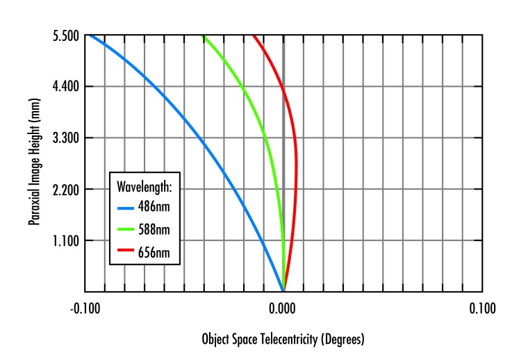
How is telecentricity quantified? In the data sheets, telecentricity is often specified as an angle, usually together with a wavelength. This angle describes the residual angle of the object space chief ray. Since the ideal target is 0°, these are usually very small angles, say in the range of < 0.1°. An exact 0° angle is usually never achieved, because the angle ultimately depends on the wavelength of the light and most lenses are designed for an entire range of wavelengths, not just a single wavelength. It is therefore necessary to find the best possible compromise between the residual angle and the desired wavelength range at which the lens is to be used. Figure 2 shows an example of data of a telecentric 1X lens where the angle of the chief ray relative to the optical axis is shown for three different wavelengths. The y-axis demonstrates the position of the chief ray on the sensor. By definition, the angle at the center of the image is 0° – here is where the chief ray coincides with the optical axis.
When moving from here towards the image corner, the chief ray angle is in most cases described by a monotonic function – i.e. the further away from the image center, the larger the angle. In the example, the angle at 5.5 mm (corresponding to a sensor with 11 mm diagonal, 2/3" format) reaches a value of ~0.1° for blue light of wavelength 486 nm. However, the function does not always have to be monotonic and may differ, especially for other wavelengths. For red light (656 nm), the angle at 5.5 mm is only about 0.015°, and the curve even shows a sign change. At approximately 4.4 mm image height, the angle is 0° again. As a rule, it is therefore advisable to use a graph of this type instead of referring to a single value in a spec sheet, which may not be representative of the parameters relevant to the application. Furthermore, it is recommended to recalibrate an optical measuring system when working monochromatically and changing the wavelength of the light.
Summary
This article presents the applicational advantages as well as the functionality of object space telecentric lenses. Finally, it should be noted that image space telecentric lenses can also offer benefits. These are less sensitive to the exact position and location of the sensor in the camera. Furthermore, the radiometric effect described in the cos4 law is avoided: the intensity of the light will decrease from the center away to the image edge with the factor cos4(CRA), where CRA stands for the image space chief ray angle. For a telecentric lens, this angle is 0°, so the factor is 1. Provided that the lens does not have mechanical vignetting in conjunction with the sensor used, no apparent drop in relative illumination will therefore be observed. A final advantage of image space telecentrics kicks in when using precise optical filters installed between the lens and the camera. These filters are usually designed for an angle of incidence of 0°. The more one deviates from this angle, the more the filter response shifts to shorter wavelengths. The filter transmission would thus not be uniform over the sensor area, which is usually not acceptable for precise measurements in e.g. fluorescence or hyperspectral imaging.
In the field of optical metrology, the factor of the lower sensitivity to the exact sensor position is usually the most important. However, in order to achieve the best possible measurement results, it is recommended to use bi-telecentric lenses, which combine the advantages of both concepts. ¢
Autor
Dr. Boris Lange, Manager Imaging Europe, Edmund Optics
most read

There’s a Large Hippo Resting in the Mud
Virtual Video Safaris for Blind and Visually Impaired People
Targeted Grasping of the Right Object
2D Images Combined with Deep Learning Enable Robust Detection Rates
Hyperspectral Imaging for Surface and Layer Analysis
Optical Wafer Inspection
MWIR system camera for continuous industrial operation
Entry into infrared imaging
Optical Metrology Technology: Focus-Variation and its Advanced Extensions
Basics of Measurement Technology


